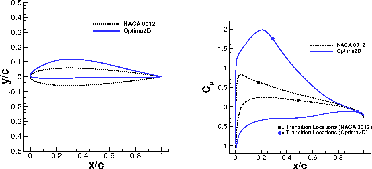

But enough of a rise away from the very low values that it would be worth using an airfoil with enough camber that the low drag range of Cl's is centered at around that value. It is designed to have a laminar bucket between CL.1 and CL.65, but also have the ability to achieve.

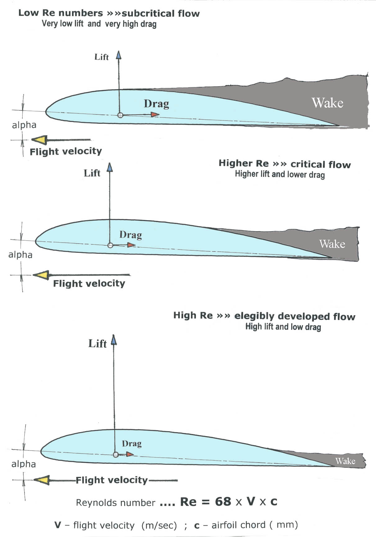
I set the camber to 1.2% and the thickness to just a hair under 10% for this example.Įven building heavy and ballasting to 7 lbs at 25G's the required Cl only rises to 0.247. The S414 is a slotted, natural-laminar-flow airfoil. The upper wing surface includes: a convex front profile portion extending from a leading edge to a largest-thickness point located corresponding to 38 of a wing chord length. 631-412 are the laminar-flow, or low-drag, sections and the airfoil designated as NACA 23012 is a conventional airfoil designed during the 1930's. The airfoil is very limited in what you can do with camber and thickness. An upper wing surface of a laminar-flow airfoil for decreasing an undesirable head-lowering pitching moment around an aerodynamic center of the airfoil. The extent of laminar flow is limited to about 70-percent chord by. 3.) By appropriate airfoil shaping, extensive ( 30-percent chord) lamina r flow can be achieved on both the upper and lower wing surfaces. The laminar flow wing is usually thinner than the conventional airfoil, the leading edge is more pointed and its upper and lower surfaces are nearly symmetrical. A second approach is to employ a natural-laminar-flow (NLF) airfoil to achieve a lower profile-drag coefficient. A flapped natural laminar flow airfoil for general aviation applications, the NLF(1)-0215F, has been designed and analyzed theoretically and verified. And at 75 lbs of lift the Cl rises to 0.106. Laminar flow airfoils were originally developed for the purpose of making an airplane fly faster. So our 4.5 sq foot wing at 60lbs of lift and at 400 mph only needs to work at a Cl of a mere 0.087. Just for giggles a 2 meter span wing with 650 sq inches, or 4.5 sq feet, of area and 3 lbs weight will need to generate 60 to 75 lbs of lift during the circuit shown by Sparky.Ĭheating a little and being lazy I tend to use NASA's Foilsim for quick answers and get a feel for such things. Laminar airfoils are optimally designed at high Reynolds numbers to have long runs of laminar flows without significant separation to provide high lift with low.

With the G load more or less in the 20 to 25G range you can begin looking at what the lift coeficient will need to be on your wing and with that to begin picking an airfoil which has lower drag values for this sort of lift range. An upper wing surface of a laminar-flow airfoil for decreasing an undesirable head-lowering pitching moment around an aerodynamic center of the airfoil.


 0 kommentar(er)
